
What Is E.L.S.T.?
Electroluminescent Super Thin (E.L.S.T.) is an integrated, ultra-thin lighting system for aircraft panels that illuminates legends, labels, borders, and other graphics directly from the panel surface. At only .020 inch thick, it provides a clean, uniform glow without bulky conventional lighting hardware.
In Brief
- Thickness: .020 inch — thin enough to add illumination to many flat or curved surfaces.
- Purpose: Integrated illumination for panel legends and graphics in legacy-aircraft cockpit upgrades.
- Light quality: A refined, even glow designed as light to be seen, not light to see with.
- Power: Operates from 120 VAC at 400 Hz supplied by a dedicated inverter; it does not connect directly to aircraft DC power.
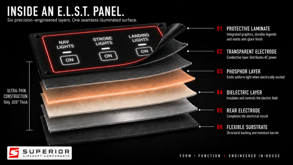
How E.L.S.T. Works
The system uses an electrically excited phosphor layer placed between conductive and insulating layers. When the specified alternating current is applied, the phosphor emits a smooth, uniform glow through the finished graphic surface. The complete assembly remains exceptionally thin while integrating the artwork, electrical conductors, light-producing material, and protective surfaces into one system.
Six-Layer Construction
| Layer | Component | Function |
|---|---|---|
| 01 | Protective laminate | Integrates the graphics and durable legends while providing a matte, anti-glare finished surface. |
| 02 | Transparent electrode | Distributes AC power across the illuminated area while allowing emitted light to pass through. |
| 03 | Phosphor layer | Produces uniform light when electrically excited. |
| 04 | Dielectric layer | Insulates the assembly and controls the electric field. |
| 05 | Rear electrode | Completes the electrical circuit across the light-producing layer. |
| 06 | Flexible substrate | Provides structural backing and a moisture barrier for the thin-film assembly. |
What E.L.S.T. Delivers
- Integrated illumination: Labels and graphics illuminate from the panel surface for a clean, purpose-built appearance.
- Uniform output: The light-producing layer provides an even glow without concentrated hot spots.
- Minimal profile: The .020-inch construction adds lighting with very little thickness and can accommodate many curved surfaces.
- Refined cockpit appearance: Supports the form-and-function standard expected from a custom Superior aircraft panel.
- Efficient operation: A complete panel draws less than 0.5 amp under the specified system configuration.
What the Glow Is Designed to Do
E.L.S.T. provides subtle, controlled illumination that makes legends and panel graphics visible. It is not intended to replace primary cockpit, task, flood, or emergency lighting.
Power and Electrical Requirements
Aircraft electrical systems supply DC power, but an E.L.S.T. panel requires AC power. A dedicated inverter converts the aircraft’s 14- or 28-volt DC supply to the required panel input.
- Required inverter output: 120 VAC at 400 Hz while connected to aircraft DC power.
- Aircraft supply: Confirm the battery and charging system provide full 14 or 28 VDC, as applicable.
- Circuit protection: Use a 0.5-amp circuit breaker or a W31-style breaker-switch.
- System draw: A complete panel draws less than 0.5 amp.
- Dimmer: A dimmer is not recommended. Superior sets the brightness for proper appearance, longevity, and protection of both the E.L.S.T. panel and inverter.
IMPORTANT: Never connect an E.L.S.T. panel directly to aircraft DC power. The panel must be powered through the specified inverter producing 120 VAC at 400 Hz.
Installation Restrictions
The completed E.L.S.T. assembly is conductive and is manufactured around the approved panel design. Its circuitry can be damaged by drilling, cutting, trimming, pinching, or other post-production changes.
- Do not drill, cut, trim, or modify the completed panel. Any new hole or cut can interrupt or short the internal circuitry.
- Do not overtighten screws or installed equipment. Excess clamping pressure can pinch the conductive material and create a short.
- Protect the wire leads. Route and secure them to prevent chafing, pinching, grounding, or strain at the panel connection.
- Finalize the layout before manufacturing. Confirm equipment, mounting details, labels, and graphics with the installing avionics shop before the design is released for production.
- Return required changes to Superior. Contact Superior Aircraft Components before attempting any repair or modification.
Getting Started
You may begin planning and designing an E.L.S.T. panel at any time. Detailed production drawings should not be finalized until the aircraft arrives at the avionics shop. The installer will confirm the equipment being used, identify installation-specific requirements, and recommend any layout changes before the non-modifiable E.L.S.T. assembly is manufactured.
If the E.L.S.T. Panel Does Not Illuminate
Electrical Safety
De-energize the aircraft circuit before continuity testing. The 120 VAC scoring procedure must be performed only with the Superior Aircraft Components test kit and its instructions by qualified personnel. Do not improvise a connection to household or other mains power.
- Inspect for physical causes. Look for modifications, drilled holes, cuts, overtightened screws, pinched areas, damaged leads, or hardware pressing into the conductive assembly.
- Check for an unintended short. Using a multimeter on a de-energized system, check the panel circuitry and test each wire lead individually to aircraft ground. If a short is indicated, stop and contact Superior Aircraft Components.
- Verify aircraft DC power. Confirm the aircraft battery or electrical source is producing full 14 or 28 VDC, as applicable, while supplying the inverter.
- Verify inverter output. With the inverter connected to aircraft DC power, confirm an output of 120 VAC at 400 Hz.
- Score the panel only when no short is present. Contact Superior Aircraft Components for the approved test kit. The panel may be scored using 120 VAC at 60 Hz in accordance with the supplied instructions.
- Observe the scoring result. A properly responding panel should produce a green glow during the scoring test. It can then be reconnected to the 120 VAC, 400 Hz inverter.
- Contact Superior if the panel still does not glow. A panel that will not produce the expected green glow during the approved scoring test may require factory evaluation, repair, or replacement.
Frequently Asked Questions
Can I drill through or modify the panel after it is made?
No. The complete E.L.S.T. panel is conductive. Drilling, cutting, trimming, or other modification can damage or short the circuitry.
Can I connect it directly to aircraft power?
No. Aircraft power is DC. E.L.S.T. requires a dedicated inverter that supplies 120 VAC at 400 Hz.
Should I install a dimmer?
No dimmer is recommended. Brightness is set by Superior to protect the panel and inverter and to support long service life.
How bright is E.L.S.T.?
It produces a subtle, uniform glow intended to make labels and graphics visible. It is light to be seen, not light to see with.
What circuit protection is required?
Use a 0.5-amp circuit breaker or a W31-style breaker-switch. A complete panel draws less than 0.5 amp.
Support and Related Information
Superior Aircraft Components | 5955 Chandler Rd., Hutto, TX 78634 | 512.522.2456 | info@superioratx.com
Product page: superioraircraftcomponents.com/elst/
This guide combines Superior Aircraft Components’ product information with the company’s installation and troubleshooting guidance. Installation and testing should be completed by qualified personnel in accordance with the aircraft’s approved documentation and all applicable requirements.


